

HDR Primer
Abstract
Section titled “Abstract”HDR rendering presents a lot of new challenges compared to non-HDR (or SDR) rendering. That requires changes in the rendering pipeline and the content authoring process. As an integral part of any game, the UI also needs some changes that will be in this document. In order to fully understand those changes, a strong understanding of the whole HDR rendering process is required. This document will present the following 3 areas in order:
- The terminology and (simplified) science behind the different color rendering pipelines
- Common approaches for calibrating the color so it looks as designed
- Interaction with the UI system, namely the Gameface SDK
Introduction to colorimetry
Section titled “Introduction to colorimetry”This section is intended for familiarizing the reader with the main concepts of HDR rendering and the related terms. It is by no means a complete guide so use it with care.
No image device is capable of capturing and displaying the full spectrum of colors visible to the human eye. Consequently, image devices record, edit, display, or output a subset of those colors. This range of reproducible colors is known as the device’s color space or color gamut.
Standard-gamut versus wide-gamut color
Section titled “Standard-gamut versus wide-gamut color”Traditional computer displays and HDTVs support a limited color space that’s based on a decades-old industry standard called Rec. 709 (ITU-R Recommendation BT.709, sometimes referred to as BT.709). Rec. 709 devices (and the video content created for display on them) have standard-gamut color, the constrained color palette you see whenever you view a broadcast HDTV show, DVD, or Blu-ray disc. A more recent generation of displays—including 4K televisions and computer displays can render a much wider palette of colors. These wide-gamut color devices display more vivid and lifelike hues (in addition to all the hues that standard-gamut devices can display). Accordingly, the video industry has adopted a wide-gamut color standard called Rec. 2020. Although most currently available wide-gamut devices support only a subset of the colors contained in the full Rec. 2020 specification, future imaging devices should be able to render more and more of those hues.
High dynamic range (HDR)
Section titled “High dynamic range (HDR)”Additionally, some newer imaging devices can display extra levels of brightness in each color component (red, green, and blue) in a way that more closely reproduces how the human eye perceives contrast. These high-dynamic-range (HDR) displays typically process video at 10 bits per color component rather than 8 bits. The additional color data lets HDR displays render more discrete steps from the minimum to a maximum brightness value in each color, creating more realistic color transitions and revealing more detail in both shadows and highlights. The new standard for these HDR displays is Rec. 2100 which uses the same color space as Rec. 2020 but defines aspects of the HDR displays like bit depth, transfer function (more on that later), etc.
Color spaces
Section titled “Color spaces”There are many color spaces used throughout the years, but the most practical ones are trichromatic RGB color spaces, which define every color as a combination of a Red, Green and Blue value.
RGB color spaces are often displayed for comparison mapped onto a grid representing either the CIE XYZ or CIE xyY color space. We won’t go into detail about that but it’s usually used as an intermediate format as it’s not practical for storage and many of the values represent colors that don’t physically exist.
One often-quoted metric for how well a color space represents our experiences is Pointer’s Gamut. Pointer’s Gamut is a collection of measured chromaticities from diffuse reflections in the real world. It is intended to cover the space of colors we see on a daily basis. It is important to remember that it only covers diffuse interactions, so representing all of Pointer’s Gamut is not a guarantee that every color can be represented
This is the color space anyone doing real-time rendering, such as game development, is likely intimately familiar with even if they aren’t aware of it. sRGB is the space our content is authored and displayed in today because it is the standard that monitors are generally built toward. As can be seen in the diagram below, it occupies a relatively small portion of the visual locus. This limitation is governed by the purity of the primaries. Since sRGB doesn’t allow negative values to be represented, nothing can be more saturated than the color primaries, restricting the colors that can be represented.
sRGB covers only 33% of chromaticities in the visual locus and only 69% of Pointer’s gamut. In addition, the standard limits maximum luminance to only 80 nits. This greatly restricts the portion of the real world that can be faithfully represented in this color space. sRGB’s white point is a standardized one known as D65. (As with many things color it was a standard set by CIE) D65 corresponds to the white perceived at noon under an overcast sky. This also equates to the correlated color temperature of roughly 6500K.
As a historical note, sRGB was developed by Microsoft and HP back in the mid-1990s to standardize the display and printing of color for PCs. It has evolved into a ubiquitous standard on the internet. In practice, many monitors that support sRGB as their standard actually do exceed the standard color space. Typically, this is in the realm of luminance, with 200 or even 300 nits being common. In practice, the higher luminance gets used to adjust for use in brighter environments, with most users having their monitor set nowhere near maximum brightness. The monitors still only deliver at best 1000:1 static contrast ratios as backlight leaking and reflections of ambient light lead to black pixels really being brighter than 0.1 nits.
Rec.709
Section titled “Rec.709”As mentioned previously, Rec.709 is the specification for HDTV color. For the purposes of game development, it is very similar to sRGB. It shares the same color primaries and thus its gamut of chromaticities is identical. It does have a somewhat different encoding, partially due to the expectation of a different viewing environment. TVs are expected to be viewed in a dimmer environment than computer monitors, altering the perception of contrast. Because of this, it specifies a different gamma function.
BT.2020 / Rec.2020
Section titled “BT.2020 / Rec.2020”BT.2020 is the color space defined to be used for UHD displays. As can be seen in the diagram below it is based on completely monochromatic red, green, and blue primaries. This produces a very large color gamut that covers 63% of visible chromaticities and 99% of Pointer’s gamut.
scRGB is a color space that was introduced by Microsoft with Windows Vista. It offers an expanded gamut while maintaining compatibility with sRGB primaries. The color space uses a linear encoding with a fixed point that permits a range of [-0.5,7.5]. The key bit is that all colors in the [0,1] range match sRGB colors exactly. While scRGB is technically only defined for fixed-point encodings, one can easily imagine that the same concept extends to floating-point encodings as well. Naturally, the range restrictions are lifted under such a scenario allowing the representation of a very wide gamut and very high dynamic range. As with true scRGB, an FP16 floating-point representation has been available since Windows Vista. This color space is extremely useful because it is defined such that it can be easily composited with other desktop elements that are authored in straight sRGB. As floating-point isn’t officially listed in the scRGB standard, it isn’t technically scRGB. However, it appears likely that there will be an amendment or extension to cover this in the future, so for the purposes of this document we’ll just use the scRGB term for floating-point data encoded in this manner for simplicity
Rec. 709 vs. Rec. 2020 (2100)
Section titled “Rec. 709 vs. Rec. 2020 (2100)”A standard image shown in the CIE xyY color space is displayed below:
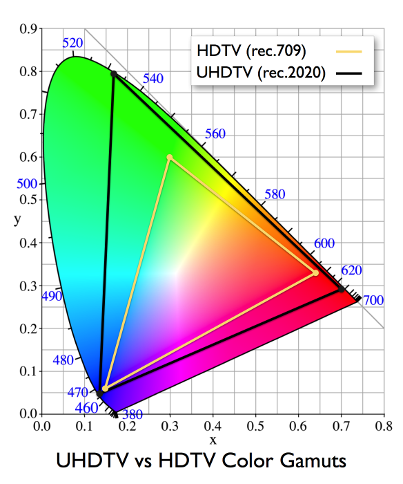
Color primaries for a certain color space define the endpoints of the display triangle (for a trichromatic color space). All color spaces can be defined in terms of the CIE xyY color space.
Note that the numbers on the curve denote the wavelength (in nm) of a component. If an endpoint lies exactly on the curve, it represents a single wave. If it is somewhere in the middle of the spectrum, it’s a combination of different waves.
On a standard SDR display, there will be no noticeable difference but you can just think of it as a larger representable color spectrum.
Converting Between Spaces
Section titled “Converting Between Spaces”If you weren’t already aware, converting between these different RGB color spaces is predominantly done via a simple linear transform (once colors are in a linear representation). The standard way of describing the transforms is via the XYZ space as an intermediary. (sRGB -> XYZ -> BT.2020) Naturally, the 3x3 matrices representing transforms to and from XYZ space get concatenated in an optimized scenario. The reason you want to transform from space to space rather than simply mapping (1,0,0) in sRGB to (1,0,0) in BT. 2020 is that your colors will shift, and artists may wonder what has happened to their work. (“Why does the character look like he has a sunburn?”) The gamut mapping section later in this paper offers some perspective on the pros and cons of remapping rather than transforming colors. In addition to simply changing the color primaries, it may be necessary to adjust the white point of the image as well. The standard way of doing this is through a Chromatic Adaptation Transform (CAT). The common CAT solutions are the Bradford or Von Kries transforms. These convert the colors to an LMS color space, then scale by destination white/source white (also in LMS space), and finally convert back from LMS space. As the transform to LMS space in both Bradford and Von Kries is simply a 3x3 matrix multiply, the entire CAT can be collapsed into a single 3x3 multiply, just like the transform of primaries. The final complete color transform generally looks like the pseudocode below:
RGB = ToLinear( inRGB) // remove non-linear encodings, like gammaXYZ = mult( RGB_2_XYZ_mat, RGB)LMS = mult( XYZ_2_LMS_mat, XYZ)LMS = LMS * ( outWhite_LMS / inWhite_LMS)XYZ = mult( LMS_2_XYZ_mat, LMS)RGB = mult( XYZ_2_RGB_mat, XYZ)outRGB = FromLinear( RGB)It should be noted that the only steps not representable as 3x3 matrix multiplies are the decoding/encoding from/to non-linear representations. As a result, the optimized solution will typically collapse the transformations into a single matrix multiplication.
Definitions
Section titled “Definitions”cd/m2 – The candela (cd) is the base unit of luminous intensity in the International System of Units (SI); that is, how bright an object is. A common wax candle emits light with a luminous intensity of roughly one candela. Not to be confused with the lux measurement unit which determines how much light an object receives.
Nits – A non-SI unit used to describe the luminance. 1 Nit = 1 cd/m2.
HDR – High Dynamic range. It is a technology that improves the brightness & contrast range in an image (up to 10000 cd/m2). HDR displays can simultaneously display very bright and very dark areas.
The human eye can perceive a vast range of brightnesses, from dimly-seen shapes under the moonlight to the glare of sunlight reflected from metallic surfaces. This is termed the dynamic range and is measured by the luminance of the brightest displayable white, divided by the luminance of the deepest black. sRGB, with a peak luminance of 80 cd/m², has a viewing flare of 5% (4 cd/m²) giving a total dynamic range of 20x.
Display P3, which is often used with a peak white luminance of around 200 cd/m² and a black luminance of 0.80 cd/m², has a total dynamic range of 250. The luminance limits are set by power consumption and heating if the entire display is set to the maximum brightness white; and also user comfort, as the white is a typical background for text and represents a “paper white” or “media white”. In the broadcast industry, this is termed standard dynamic range (SDR). It falls far short of what the human eye can perceive.
In nature, very bright objects occupy a very small fraction of the visual field. Also, we can see detail in an almost dark room. By taking advantage of these two aspects - scene-by-scene lightness changes and localized highlights, a display can produce a wider dynamic range by turning down the backlight in dark scenes and turning it up in bright ones; in addition, if each small portion of the screen has its own backlight, small highlights much brighter than a paper white can be produced, for a small area and for a small time. This is called High Dynamic Range (HDR).
As an example, the broadcast standard ITU BT.2100, with the PQ electro-optical transfer function, will display a paper white at around 200 cd/m². But the deepest black is 0.001 cd/m²; and the peak, short-term, small-area white is 10000 cd/m² giving a total dynamic range of ten million. While this is a theoretical peak, reference monitors with a peak luminance of 1000 cd/m² to 4,000 cd/m² are in widespread use for movie and TV production. Consumer devices with peak luminances of 500 to 1200 cd/m² are becoming common.
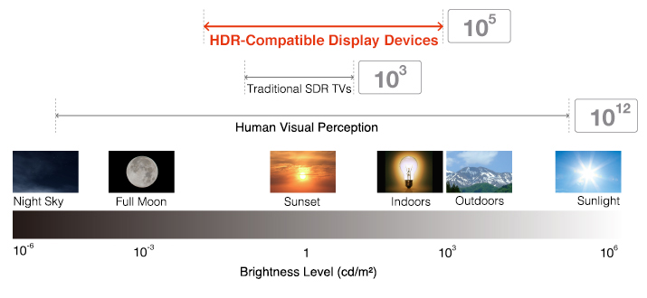
SDR – Standard Dynamic range. It refers to the brightness/contrast range that is usually available in regular, non-HDR televisions usually with a range of up to 100-150 cd/m2. This term came into existence after HDR was introduced
WCG – Wide Color Gamut. Color gamut that offers a wider range of colors than BT.709. DCI-P3 and BT.2020 are examples of WCG offering a more realistic representation of images on display devices.
EOTF – electro-optical transfer function. A mathematical transfer function that describes how digital values will be converted to light on a display device. Gamma 2.2 is an EOTF. In simple terms, this is the transformation that every pixel undergoes when the GPU sends the data to the display device.
OETF – optical-electro transfer function. A mathematical transfer function that describes how the light values will be converted to digital values typically within cameras. Basically, the inverse of the EOTF.
OOTF – opto-optical transfer function. This transfer function compensates for the difference in tonal perception between the environment of the camera and that of the display. In the conventional SDR system (BT.709), the OETF on the camera side is a power function and the (less than unity) coefficient (gamma value) is typically around 0.45 (1 / 2.2), the EOTF on the monitor side is a power function with a 2.4 coefficient. This mimics the physical characteristic of the original cathode ray tube (CRT) displays, and it is not strictly a reverse characteristic to the camera so a slight ~1.2 power-law remains, this is called OOTF (Opto-Optical Transfer Function) and is the characteristic of the whole system. Thus, OOTF is a conversion function between real scene and display light, and is not necessarily a linear relationship. The OOTF represents end-to-end image conversion between a real scene and a monitor display and includes an adjustment that is an aesthetic choice of the producer.
PQ – PQ (or Perceptual Quantizer, also referred to as ST.2084) is a transfer function devised to represent the wide brightness range (up to 10000 Nits) in HDR devices. PQ is an example of an EOTF.
HLG – HLG (or Hybrid Log-Gamma) is a transfer function devised to represent the wide brightness range in HDR devices. HLG is quite compatible with existing SDR devices in the SDR range. HLG is an example of an EOTF.
Sample program for displaying ST2084
Section titled “Sample program for displaying ST2084”import numpy as npimport matplotlib.pyplot as plt
def st2084inverse(nits): nits01 = nits / 10000.0 m1 = 2610.0 / 4096.0 / 4.0 m2 = 2523.0 / 4096.0 * 128.0 c1 = 3424.0 / 4096.0 c2 = 2413.0 / 4096.0 * 32.0 c3 = 2392.0 / 4096.0 * 32.0 cp = pow(abs(nits01), m1) hdr10val = 1024.0 * pow((c1 + c2 * cp) / (1 + c3 * cp), m2) return hdr10val
def st2084(hdr10val): hdr_norm = hdr10val / 1024.0 m1 = 2610.0 / 4096.0 / 4.0 m2 = 2523.0 / 4096.0 * 128.0 c1 = 3424.0 / 4096.0 c2 = 2413.0 / 4096.0 * 32.0 c3 = 2392.0 / 4096.0 * 32.0 cp = pow(hdr_norm, 1.0/m2) nits = 10000.0 * pow(np.maximum(0.0, cp - c1) / (c2 - c3 * cp), 1.0/m1) return nits
t3 = np.arrange(0.0, 1024.0, 0.1)plt.xlabel('HDR10 value')plt.ylabel('output nits')plt.plot(t3, st2084(t3), 'k')plt.grid(True)plt.show()HDR Signal to light mapping
Section titled “HDR Signal to light mapping”The graph below describes the mapping of light levels for various transfer functions. The vertical axis shows the signal values on a scale of 0-1 with 0 being black and 1 being white. This is done to make the signal range, and bit depth agnostic. The horizontal axis shows the light level in the Nits of a display device.
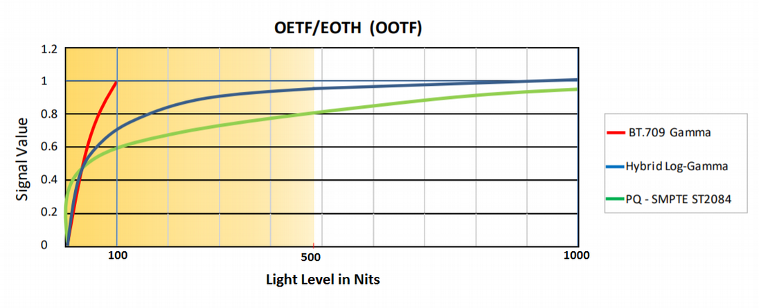
Human beings are more sensitive to changes in the darker region compared to changes in brighter regions. This property is also exploited in HDR systems providing more granularity in darker regions compared to brighter regions. The graph above depicts that the light level range in the darker region is represented by a larger signal value range compared to the brighter regions – meaning more granular representation in darker regions. While this is more evenly distributed for the BT.709-based displays, it becomes less granular for HDR displays in the brighter regions. In the case of HLG, more than half of signal values are represented for light-level between 0-60 Nits and the remaining signal values are represented in the 60-1000 Nits range. Similarly, in the case of PQ ST2084-based displays, approx. half of the signal values are represented for light-level between 0-40 Nits and the remaining half of signal values are represented in the 60-1000 Nits range.
According to the graph, HDR HLG is similar to BT.709 in lower brightness regions, therefore offering better compatibility with the existing SDR display devices. However, HDR PQ is quite different from BT.709. If we try to display the PQ HDR image on an SDR display, darker regions represented by PQ will invariably become brighter thereby reducing the contrast levels of the image, the result being a washed-out image (see below)
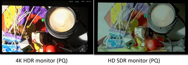
The HLG-based image looks much better on an SDR monitor:
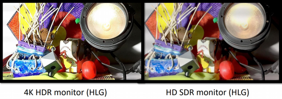
While PQ-based transforms offer promise to display the best quality results on HDR-enabled monitors, in comparison to HLG, it requires proper tone mapping by display devices.
HDR Rendering
Section titled “HDR Rendering”HDR rendering started getting popular in the early 2000s. At that time, HDR displays weren’t a thing yet so an alternative approach must be used.
As a side note, HDR rendering is vastly used for accurate lighting models and UI, as something that is not lit, may not be part of an HDR pipeline. We’ll look into this in more detail when talking about the integration of UI systems in an HDR pipeline.
SDR pipeline
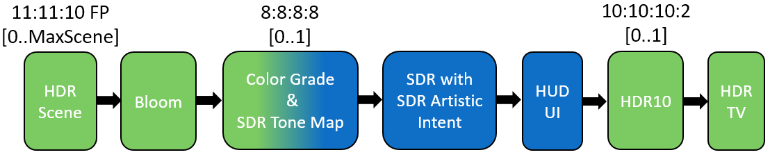
Section titled “SDR pipeline”The basic HDR rendering pipeline on an SDR target is to use intermediate targets that allow for greater precision, which are then tone mapped into representable (i.e. [0-1]) space. The most widely used tone map operators are Reinhard (x/(x+1)) and Filmic (ACES).
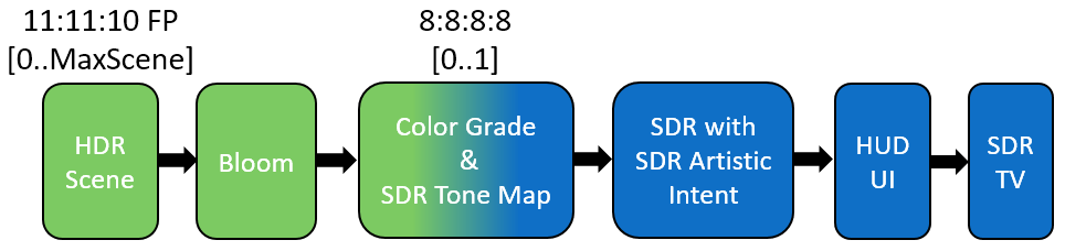
When rendering to an HDR TV there’s an additional conversion to the HDR10 format (Rec.2020 + ST.2084 transfer function)
HDR pipeline
Section titled “HDR pipeline”With the advent of HDR TVs, we can now simply display the HDR values themselves without any adjustment.
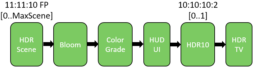
Unfortunately, HDR displays vary wildly in display capabilities. In the early days, there was no standard so every manufacturer labeled their products as “HDR” although they would be capable of producing luminosity only slightly greater than on an SDR display, the brightness detail was reduced in the SDR range in order to be able to light the pixels more at the upper end, etc. It wasn’t until the HDR10 standard emerged that we actually got some hard specs (e.g. 1000+ nit peak brightness, 10-12 bits per channel, etc.) that needed to be covered so a display is classified as “HDR” (or HDR10).
Note: HDR10+ is an additional standard that builds on top of HDR10 and allows adding metadata on a frame-by-frame basis so each frame can have a different transfer function.
Even though HDR TVs are capable of displaying HDR scene values as HDR to the consumer, some mapping is still required to ensure that values in the HDR scene that are brighter than what the HDR TV can display will still be visible. We refer to this as “HDR display mapping” because it maps a full range of HDR values to a reduced range of HDR values suited to a specific TV/display’s capabilities, while still keeping the SDR values in the range of Black to White [0..1] the same.
Why HDR display mapping is needed
Section titled “Why HDR display mapping is needed”HDR display mapping is needed because different HDR TVs have different maximum brightness levels. For example, one TV could output a maximum of 600 nits, while another could output 2000 nits (with nits being a standard measurement of brightness). If the maximum brightness value of an HDR scene is 1600 nits, a 2000 nit TV will be capable of displaying all the values in the HDR scene. However, on a 600 nit TV, all values above 600 nits will be naturally clipped by the TV to 600 nits, thus losing all the details in those bright areas of the scene. It is therefore very important to know what the maximum perceived brightness of the attached TV is. This can be determined by using a calibration method discussed later.
Calibrating the TV
Section titled “Calibrating the TV”HDR TVs can vary wildly with regards to HDR capabilities which affect image quality. Entry-level TVs can struggle to physically reproduce HDR, the peak brightness might not be great, it might use whole panel illumination instead of local illumination, etc. To compensate for these differences, games should allow the consumer to calibrate the game’s HDR image. Two different modes are usually employed, subjective calibration where the user adjusts the image until it looks good, and objective calibration where test patterns are shown to determine the TV’s capabilities.
Detail in Brights
Section titled “Detail in Brights”HDR values above what the TV can display will get clipped, therefore losing details in the brights. We need to determine the maximum perceived brightness of the TV so that the very bright HDR values in the scene can be mapped to the maximum brightness of the TV. The calibration image renders a value into the scene which represents 10000 nits, the maximum brightness of the ST.2084 spec. A smaller image is then rendered with the current brightness. The user adjusts the current brightness value until he can no longer distinguish between the two images. For example, if the TV can display 1000 nits, then values rendered into the scene representing brighter pixels than 1000 nits will still be perceived as 1000 nits.
Detail in Darks
Section titled “Detail in Darks”Most games have a video option in a menu to determine display gamma. This can be used to correct contrast using a power function in a pixel shader, in order to see the correct amount of detail in the darks. This adjustment is very important when the TV is in HDR mode. Without the proper adjustment, the HDR image will look “flat” and dull compared to the SDR image. It is important to render the calibration screen in the center of the screen because the viewing angle on some LCD TVs can change the contrast of the image even from a small angle. For example, if rendering the calibration image on the side of an LCD screen, the determined display gamma value will be slightly different from when rendering in the center of the screen. Using a flashing image works well for this calibration because it’s easier for the user to determine when the center calibration block becomes invisible. Note that applying some contrast adjustment will change the maximum HDR scene value, which is important to do effective HDR display mapping, therefore the contrast adjustment function also needs to be applied to the maximum scene value going into HDR display mapping. A typical value is in the range of [0.85..1.25].
Note: There is some misuse of the term contrast, which is sometimes used as gamma adjustment, but that is incorrect.
Overall Brightness
Section titled “Overall Brightness”Entry-level HDR TVs do not have a great peak brightness. To be able to show HDR, it must sacrifice the brightness of the SDR range of the image, which can make the image look worse when compared to an SDR TV. For example, a good HDR TV will output 100 nits when rendering 100 nits, but an entry-level TV might only output 30 nits when rendering 100 nits. It is therefore necessary to allow the consumer to adjust the brightness of the SDR range in the image. This is done by adjusting the paper-white nits value. Note that as paper white goes higher, the potential range for HDR is reduced. Therefore, it is recommended to show an HDR image with lots of detail in the bright so that the consumer can understand the compromise between a brighter SDR range with a smaller HDR range. A typical value is between 100-300 nits.
Color Saturation
Section titled “Color Saturation”Display panels of HDR TVs have the capabilities to produce very bright and colorful images since they can all produce colors outside of the Rec.709 color space. When in SDR mode, TVs often use a color gamut expansion to make the SDR image look more colorful. When rendering the theoretically correct colors in HDR mode, the image can often look less colorful than when in SDR mode. A solution to this problem is to do color gamut expansion within the game. This option control how much color gamut expansion should be applied.
When using objective calibration with test patterns, take care not to apply the display gamma or any soft shoulder on the actual brightness calibration block, because this will change the perceived max brightness value. For example, when trying to determine the max perceived brightness of the TV, using a display gamma adjustment will result in the wrong value.
Content authoring
Section titled “Content authoring”A practical path to utilizing UHD in the near term
Section titled “A practical path to utilizing UHD in the near term”As with all engineering, game development is an exercise in compromise. The goal in supporting UHD class displays isn’t to simply generate content targeted directly to the native BT. 2020 color space with a dynamic range that tops out at 1000+ nits. The goal is to create a great game that looks fantastic on the majority of displays that your customers have (sRGB-based) and to enhance your pipeline to also produce images that make good use of these new, better displays. Given the complexity and cost of developing content for a game, it is generally impractical to expect UHD and sRGB assets or convert over the art flow to generate most art in these new wider color spaces.
Here are the core principles recommended by NVIDIA:
- Author content with sRGB primaries as today
- Render high-quality HDR data using physically-based shading
- Analyze content for dynamic range produced
- Watch for hacks with luminance levels
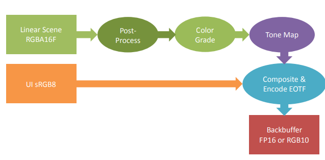
- Perform all rendering operations with respect to the sRGB primaries you use today
- Postprocess in the scene-referred space
- Motion blur, DoF, etc
- Apply any color grading to the scene-referred image
- Tone map with filmic ACES-derived tone mapper (Academy Color Encoding Standard, explained in more depth in a future section)
- Keep back buffer in FP16 scRGB (This is something not all vendors agree on)
- Composite sRGB referenced UI as normal
There’s some concern from other vendors that point out that having the buffer in FP16 format generates too much unnecessary traffic and is better to have an R10G10B10A2 back buffer using the Rec.2020 primaries and ST.2084 quantizer. The prevalent opinion is that FP16 buffers are best suited for intermediate render targets and only the back buffer should be R10G10B10A2.
sRGB Primaries
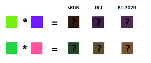
Section titled “sRGB Primaries”Keeping your content authoring in sRGB is probably the biggest item to simplify life for games in development today. Artists can continue to use the workflow they already have and, studios don’t need to re-equip the entire art staff with new monitors. Rendering using the sRGB primaries is directly related to this. sRGB primaries are what you render with today. If you were to take the sRGB content you create today and convert it into colors described by the BT. 2020 primaries before performing lighting, you’d see many different results. This happens because material interactions are relative to the color space in which they are defined. The modulation operator we all use to compute the interaction between a material and a light source will produce different results if you change the primaries. As a game developer, you don’t want your artists authoring content to see an object looking brown on their monitor, but the same object being green or purple when you run the game on a UHD class display.
The downside for UHD displays of performing all the asset authoring and rendering with sRGB primaries is that you may not be able to use the width of the gamut offered by UHD displays. The positive side of this is that you won’t have the problems of generating hues that your SDR customers cannot see and the challenges of mapping those colors sensibly. It is important to remember that even with the primary limitation you will be generating richer colors for UHD displays because highlights that would normally need to be desaturated to maintain brightness can maintain their saturation with the higher dynamic range. Additionally, the Hunt Effect applies to the mid-tones that can now be represented as notably brighter. Even though the chromaticities are the same, they may appear just as rich or richer than the wide gamut of colors displayed at SDR levels. While this is a great practical step to getting UHD content working, the general expectation is that it is an evolutionary step. As displays with a wider gamut become more widely deployed, we expect shifts to render and/or authoring primaries such as DCI. These will allow the production of the richer colors we just can’t render today.
HDR video
Section titled “HDR video”Most of today’s HDR video is in the R10G10B10A2 format using Rec.2020 primaries and ST.2084 (PQ) encoding. The idea is that after decoding the video frame pixels, data is ready to be sent directly to the GPU and forwarded to the display without any further re-encoding. This is true for video players and standalone applications which draw directly to the frame buffer, but for SDKs such as Gameface it poses a problem - the color that the SDK provides the client must not be encoded. That’s because client applications need to perform the PQ encoding themselves at the end of the pipeline. If the data was already PQ-encoded the client application would then apply it a second time for an incorrect image result. That means that video and any other resource must go through the inverse EOTF (that is, the OETF) before being passed to the client. This incurs an additional performance hit.
HDR images
Section titled “HDR images”HDR images, in contrast to HDR video, are usually encoded in an FP16 linear format, ready for lighting. This means that at the end of the pipeline the client needs to apply the PQ transfer function themselves, but that’s a good thing since client applications already have that transformation in place so practically nothing changes from the perspective of the Gameface SDK, which acts as a middle-man.
Important thing to note is that Gameface supports FP16 / FP32 formats (which usually come from the game rendering as user images), as well as BC6H (block-compressed RGB half-float format, no alpha), which is the only block-compressed format with HDR support. Other formats such as OpenEXR are not yet supported.
Tone mapping
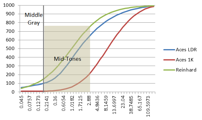
Section titled “Tone mapping”Tone mapping is the next big concern for getting good content to an HDR display. Tone mappers traditionally used in games all focus on the parametric [0-1] space, where 1.0 is just taken as maximum brightness. This falls apart with HDR displays. Applying the same tone mapper to screens with a maximum luminance of 200 nits and 1000 nits does not result in a pleasing image on both. It is the same as just turning up the brightness. You really want colors and luminance levels represented well today to remain the same. The chart below shows how remapping a tone mapper for SDR results in dim regions like middle gray being displayed at well over 100 nits, and approaching the brightness of a diffusely lit sheet of paper in your office. These facts mean that you need to use a tone map operator that is sensitive to display output levels. NVIDIA recommends using the Output Device Transform (ODT) used in the Academy Color Encoding Standard (ACES). It is a great filmic operator, and it scales to all the levels you care about in the near future.
Buffer formats
Section titled “Buffer formats”FP16 scRGB Back Buffer
Section titled “FP16 scRGB Back Buffer”As many developers might know, Microsoft Windows has supported the display of FP16 surfaces since Windows Vista. They have always been merely a floating-point representation of scRGB. So far, this has meant that the desktop compositor or the display driver applies the sRGB transform and then pushes the bits out to the monitor at whatever precision the display link is running. (While the output to the display may be 30 or 36-bit RGB, the desktop compositor presently only operates with 24-bit RGB) With the advent of the UHD display standard, integrated support is available to send the signal necessary to properly drive these displays. The application renders the frame in an FP16 buffer and leaves it in the scRGB. (sRGB primaries, linear encoding, with (1,1,1) corresponding to the sRGB white level) Finally, the swap chain must be set to fullscreen exclusive, as the desktop compositor does not yet understand UHD displays, so the display driver must be in a position to handle the data from end to end. The display driver takes the scRGB back buffer and converts it to the standard expected by the display presently connected. In general, this means converting the color space from sRGB primaries to BT. 2020 primaries, scaling to an appropriate level and encoding with a mechanism like PQ. Also, possibly performing conversions like RGB to YCC if that display connection requires it. Because the back buffer is floating-point, it can still represent the full range of colors in the BT. 2020 gamut by using negative values. The brightest possible level in this output color space is expected to be 12.5, as this corresponds to 10000 / 80. 10000 nits are the maximum brightness encoding for the UHD standard, and 80 nits are the standard for sRGB brightness, which is mapped to (1,1,1). It is important to note that the driver isn’t performing tone mapping or gamut mapping. It is expecting the output colors to be encoded by the application in a space that is output referenced and represents a good approximation of what the display device desires. The application will have already a tone-mapped and applied an appropriate ODT. The display driver is just providing a uniform abstraction to multiple different display standards.
R10G10B10A2 Back Buffer
Section titled “R10G10B10A2 Back Buffer”A more widely spread format for the back buffer is the R10G10B10A2 format which keeps the same size as a standard sRGB 8-bit-per-component buffer. The difference with the sRGB buffer is that we have more bits for the colors at the expense of alpha (which isn’t used anyway) and we need to apply the transfer function (PQ, mostly) ourselves in a shader. That’s because the widespread hardware doesn’t have support for doing the PQ-encoding. Even if it does, there’s still the cost of sending twice as much data from the GPU to the display device which is best avoided. That’s why the R10G10B10A2 format gained such tremendous popularity.
UI Rendering
Section titled “UI Rendering”During UI rendering, the UI is blended on top of the final image. In SDR, where the back buffer is a standard 8-bit sRGB image, the correct result is ensured by the hardware. With HDR, this is not always the case.
If the final scene is encoded in PQ, the result will not be blended correctly because there is no hardware support for PQ buffers.
If the final scene is encoded linearly, using a floating-point render target, there will be a serious bandwidth penalty.
In both cases, all the UI shaders must be changed to scale the luminosity.
One solution that works well with minimal changes and low-performance impact is to render the UI in a separate sRGB 8-bit image and then blend the UI buffer with the background, applying the proper linear transformation and color space correction. There are a couple of things to be on the lookout for. First, human perception is impacted by the surrounding environment. It is easy to have someone complain that white in your UI looks a bit gray when it is composited on a really bright scene. This holds doubly true if you are in a bright room. As you may recall, the sRGB standard for white is 80 nits. Due to working in brighter environments, many users have their monitors set to emit 150 or 200 nits as white. Placing a simple scale on the UI to boost the level by something like 2x will allow you to provide a brighter UI level to compensate for this sort of complaint. Second, if you have utilized extensive transparency in your UI, you may wish to consider a more complex compositing pass. Alpha blending an 80% opaque chat window over an SDR signal produces an easily readable image. However, with an HDR image and a 1000 nit highlight, that 20% bleed-through is now 200 nits making for difficult reading. Compositing the entire UI to an off-screen sRGB buffer, then compositing in a shader pass allows some extra tools to resolve situations like this. The background color can be clamped in some way, or you can simply apply a Reinhard operator of x / (x+1) to the luminance of any HDR data where the overlay has a non-zero alpha. It is pretty cheap and it keeps the HDR data safely below the level of the UI, and it preserves the color and details well.
Although the final image in the back buffer must be encoded in PQ, you can use any representation for the intermediate buffers. One encoding that works well in a range between 0 and 3000 nits is sRGB10 that is simply sRGB_to_linear(color) / sRGB_to_linear(10.0). Because this is only an intermediate buffer, you can approximate the sRGB curve with a simple gamma function using one transcendental function instead of two.
References
Section titled “References”© 2026 Coherent Labs. All rights reserved.